
Blog
Wafer or Lugged Butterfly Valve? The Practical Differences for Maintenance Teams
28 September 2026
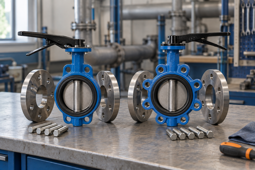
Wafer and lugged butterfly valves can perform the same basic flow-isolation function, but their bodies are supported and bolted into the pipework differently. That distinction can affect how a maintenance team removes adjacent pipework, plans a one-sided isolation, and checks the correct bolt set.
This guide focuses on those installation and maintenance questions. It does not assume that every lugged valve is suitable for dead-end service or that every wafer valve shares the same flange compatibility.
Quick answer
A wafer-pattern butterfly valve is normally clamped between two pipe flanges with bolts passing around or through the body. A lugged body has individual lugs around the valve, commonly threaded so each flange can be bolted from its own side. That can make one-sided pipework removal possible on a suitably rated lugged model. The body pattern alone is not proof: verify the exact valve’s end-of-line rating, flange drilling, face-to-face dimension, pressure and temperature limits, disc clearance, materials and bolting instructions before work begins.
Start with the maintenance task
Do not begin with a generic rule that one body style is “better”. Begin with the work the installation must support:
- Will both sides of the pipework remain connected during routine service?
- Must downstream pipework, a filter or a vessel connection be removed while the valve remains installed?
- Is the valve expected to hold pressure with one flange removed?
- Which flange standard, nominal pressure, face-to-face dimension and bolt arrangement apply?
- Can the disc open without contacting the adjacent pipe bore, lining or gasket?
- What isolation, depressurisation and lock-off procedure controls the work?
If one-sided removal or end-of-line duty is required, state that explicitly in the enquiry. “Lugged” is a construction description, not a substitute for the manufacturer’s rating.
The practical body-pattern difference
| Maintenance question | Wafer pattern | Lugged pattern | What to verify |
|---|---|---|---|
| How is the body located? | The slim body sits between two flanges and is centred by the specified flange and bolt arrangement. | Lugs around the body align with the flange holes; many designs use threaded lugs for bolts from each side. | Exact flange drilling, centring method, bolt diameter, length, quantity and thread engagement. |
| Can one side be dismantled independently? | Usually the valve depends on the complete flange clamping arrangement, so removing one side changes how it is retained. | A suitably designed and rated lugged valve may allow one flange or downstream pipe section to be removed while the other side remains bolted. | Written manufacturer confirmation for the exact model, size, pressure, flow direction and end condition. |
| Is dead-end service automatic? | No. | No. Some lugged products have a separate, often lower, dead-end pressure rating; others may not permit the duty. | Normal shut-off rating versus dead-end rating, temperature derating and whether an actuator or gearbox changes the limit. |
| What changes at replacement? | Long or through bolts and the available gap between flanges can affect removal and refitting. | Separate flange bolts and threaded lugs change the bolt list and inspection points. | Bolt condition, damaged threads, flange alignment, face-to-face dimension and access for tools. |
| Which style uses less envelope? | Often compact and light, but the full bolt path and installation gap still matter. | The lugs add body material and may increase weight or outside profile. | Published dimensions and weights for the selected size and material. |
These are planning distinctions, not universal performance claims. Manufacturer documentation for Bray Series 20/21, for example, identifies a wafer Series 20 and lug Series 21, with dead-end capability assigned to the lug version. Bray’s Series 30/31 specification gives a separate, lower dead-end pressure for the lug body than its normal bidirectional shut-off rating. GF Piping Systems similarly states that its Type 565 lug-style can be used as an end valve to allow one-sided dismantling. Those statements apply to those named product families, not to every butterfly valve.
Five checks before choosing the body pattern
1. Define the isolation boundary
Map the equipment on both sides of the valve. If a strainer, pump, filter, vessel nozzle or removable spool must be accessed, identify which side will be opened and what pressure could remain on the retained side.
A valve being closed does not by itself make maintenance safe. Follow the site’s isolation, lock-off, drain, vent and verification procedure, and use the instructions for the installed valve and actuator.
2. Ask for the exact dead-end rating
If the valve will ever retain pressure with a downstream flange or pipe removed, request the manufacturer’s written end-of-line or dead-end rating for the exact series, size, body material, seat, disc, temperature and flow direction.
Do not copy the normal closed-valve pressure rating into this duty. The available primary specifications show why: a product can have one pressure for normal bidirectional shut-off and a lower pressure for dead-end service.
3. Match the flange and face-to-face details
Record the pipe flange standard and rating, nominal size, bore, raised-face or flat-face arrangement where relevant, and available face-to-face distance. Confirm whether separate gaskets are required or prohibited by the seat design.
The live Valves4You butterfly-valve range includes wafer and lugged routes across different flange standards and materials. Final compatibility must therefore be checked against the selected product rather than inferred from the category name.
4. Check disc clearance and pipe alignment
The butterfly disc rotates beyond the body into the adjacent pipe bore. Before tightening the valve into place, confirm that the disc can move through its specified travel without striking pipework, liners, flange bores or gaskets.
Misaligned flanges should not be pulled into position with the valve bolts. Use the manufacturer’s installation sequence, torque guidance and any requirement to open the disc slightly during installation.
5. Plan the future removal job
List the bolts, access space, lifting requirement, actuator or gearbox weight, electrical or pneumatic isolation, and the condition of any threaded lugs. Record the valve identity and orientation before removal so the replacement can be checked like for like.
For a lugged body, inspect the threads and use the specified bolt engagement. For a wafer body, confirm that the replacement’s body geometry, face-to-face dimension and centring arrangement match the installation.
What to send with an enquiry
- A clear photograph of the installed valve and both flanges.
- Manufacturer, model, size and any readable body or nameplate details.
- Flange standard and pressure designation on each side.
- Medium, concentration and solids information where relevant.
- Operating and design pressure, plus minimum and maximum temperature.
- Whether the duty is isolation, throttling or automated control.
- The required maintenance task, including any one-sided dismantling or dead-end condition.
- Disc, seat or liner, body and shaft material requirements.
- Manual, pneumatic or electric operation and fail-position requirements.
- Quantity, destination, certification needs and required date.
Browse the butterfly-valve category for current product routes. If the installed details are incomplete, send photographs and duty information through the contact page. The industries overview can help frame application requirements.
Frequently asked questions
Is a lugged butterfly valve always suitable for end-of-line service?
No. Suitability and pressure limits are product-specific. Obtain the exact manufacturer’s written rating for the valve series, size, materials, temperature and end condition.
Can I replace a wafer valve with a lugged valve of the same nominal size?
Not from nominal size alone. Check flange drilling, face-to-face dimension, bore and disc clearance, pressure and temperature ratings, materials, actuation interface, weight and available installation space.
Does a lugged body let me remove downstream pipework safely?
It may support that maintenance arrangement when the exact product is designed and rated for one-sided or dead-end service. The plant must still be isolated, depressurised, drained and verified under the site’s safe system of work.
Do butterfly valves always need flange gaskets?
No universal rule is safe. Some resilient-seat designs form the flange seal and specify no additional gasket; other products have different instructions. Follow the installation manual for the selected valve.
Is wafer pattern always the cheaper option?
Do not assume a commercial outcome from body style alone. Price, availability and whole-life maintenance depend on the exact size, materials, pressure rating, approvals, actuation and project requirements.
Talk to Valves4You about the installation
Send the flange details, duty conditions and the maintenance task you need the valve to support. Valves4You can compare the current wafer and lugged butterfly-valve routes without treating the body pattern as a stand-alone suitability decision.