
Blog
Actuator Sizing: Match the Whole Valve Torque Envelope
2 November 2026
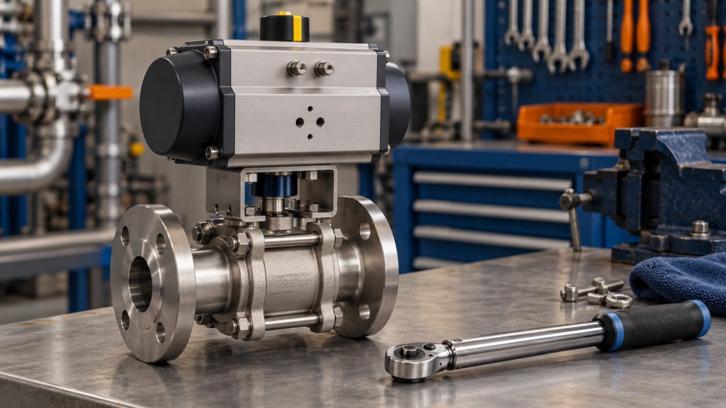
An actuator is not correctly sized simply because its headline torque is greater than one number on a valve data sheet. Quarter-turn valve torque changes through the stroke. Available actuator output can also change with position, action and supply pressure.
The useful comparison is therefore an envelope: valve torque required at each relevant point versus actuator torque available at the same point, under the specified operating conditions. The selection also needs an upper-bound check so the actuator cannot impose more torque than the valve stem and drive train can safely accept in the defined case.
Quick answer
Obtain the valve maker’s break, running and seating torque values for the actual valve, differential pressure, temperature and service. Apply only the documented service or safety factor, then compare each required point with the actuator’s start, mid-stroke and end output at the minimum available supply. Check spring and powered strokes separately where applicable. Finally, verify maximum supply or stall output against maximum allowable stem torque and the mounting train.
Why one torque figure is not enough
Published actuator tables and valve torque data use several terms. Names vary, but the underlying questions are consistent:
- What torque is needed to move away from the closed position under differential pressure?
- What torque is needed while the valve travels?
- What torque is needed to reach the fully open or seated position?
- Does opening differ from closing?
- For spring-return equipment, can both the powered stroke and spring stroke complete their required duty?
Emerson’s Biffi sizing criteria distinguish break-to-open, reseating, break-to-close, end-to-open, running and dynamic torque. Bray likewise requires the valve torque points and factor of safety to be compared with the actuator output points. These are not interchangeable with a single actuator nameplate value.
Build a point-by-point torque record
Use the valve manufacturer’s terminology in the project record. The following table is a review structure, not a substitute for the manufacturer’s sizing method.
| Comparison point | Valve evidence to record | Actuator evidence to record | Governing condition |
|---|---|---|---|
| Break from closed | Break-to-open or unseating torque | Powered or spring start output | Maximum specified differential pressure; actual service condition |
| Travel | Running torque and any stated dynamic peak | Minimum output through the corresponding stroke | Minimum available supply; opening and closing direction |
| Fully open | End-to-open requirement, where stated | End output in the opening direction | Required travel and operating time |
| Break from open | Break-to-close requirement, where relevant | Start output in the closing direction | Maximum working or differential pressure stated by the valve maker |
| Final seating | Reseating or end-to-close torque | End output in the closing direction | Required shut-off condition |
| Upper bound | Maximum allowable stem torque and drive-train limits | Maximum supply, spring or stall output for the defined case | Abnormal stop or stalled condition where the manufacturer requires this check |
Do not fill missing cells with estimates. Mark them as unknown and ask the valve or actuator supplier to confirm the sizing basis.
Six inputs that change the result
1. Exact valve and construction
Record the valve manufacturer, series, size, pressure class, seat or seal construction, stem and mounting arrangement. Torque values for a similar nominal size do not establish the requirement for another valve.
2. Process conditions
State the medium, concentration or solids where relevant, operating and design temperature, upstream and downstream pressure, and the differential pressure during each required operation. Bray explicitly notes that differential pressure across the closure element affects valve torque.
3. Operating pattern
Identify on-off or modulating duty, cycling frequency, required operating time and how long the valve may remain stationary. Emerson notes that break-to-open torque may need to account for sticking after a long closed period, while dynamic torque may matter during flow.
4. Minimum available supply
Size pneumatic or hydraulic output using the minimum pressure that can actually be relied upon at the actuator during operation, not the normal compressor or power-unit set point. For electric actuation, use the manufacturer’s supply and performance criteria for the specified voltage, duty and operating time.
5. Action on loss of supply
For spring-return equipment, compare the powered and spring torque curves separately. A package that opens comfortably on air may still fail to reach its required safe position on the spring stroke, or the reverse.
6. Permitted margin and upper limit
Confirm whether the valve torque figures already include a factor and which additional factor the valve maker or application engineering requires. Do not apply a universal percentage by habit. Then check the other side of the window: Rotork requires the valve and motor components to withstand the relevant stall torque, and Emerson’s criteria call for a maximum allowable stem torque check when an abnormal stop is credible.
What to request with an actuator quotation
- Exact valve maker, series, size, construction and stem details.
- Break, running, dynamic, seating and maximum allowable stem torque data, with units and revision.
- Medium, temperature, pressure and differential pressure for opening and closing.
- Required action, fail position, travel, operating time and cycling duty.
- Minimum, normal and maximum air or hydraulic supply, or electrical supply details.
- Required service or safety factor and whether it is already included in the valve figures.
- Actuator output at the corresponding start, travel and end positions for each direction.
- Mounting kit, coupling, key, bracket and drive-train limits.
- Calculation sheet, selected model, assumptions, exclusions and document revisions.
Keep that sizing sheet with the valve schedule. If a process condition, valve construction, supply range or required operating time changes, review the sizing rather than assuming the old actuator remains suitable.
Common mistakes to avoid
- Comparing only breakaway valve torque with a single actuator maximum.
- Using nominal supply pressure when the available minimum is lower.
- Adding an undocumented factor to torque figures that already contain one.
- Checking only the powered stroke of a spring-return actuator.
- Ignoring running or dynamic torque through the middle of travel.
- Oversizing without checking maximum allowable stem torque, mounting hardware and stall conditions.
- Reusing a calculation after the valve, duty or operating time changes.
A practical boundary
This guide explains the evidence record, not a model-specific sizing calculation. The valve manufacturer or supplier should provide the required valve torque values for the defined duty. The actuator manufacturer or package supplier should show that the selected actuator exceeds those requirements at every relevant point and remains within the valve and drive-train limits.
For a broader specification record, use the Industrial Valve Specification Checklist. You can also review the actuator range.
Discuss an actuation package
Send Valves4You the valve identity, duty, torque data, supply range, required action and controls. We can help assemble the information needed for a supported package quotation.