
Blog
Knife Gate or Pinch Valve for Slurry? A Duty-by-Duty Comparison
1 October 2026
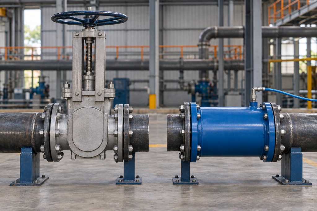
Knife gate and pinch valves can both appear on slurry duties, but the family names do not settle the choice. The useful comparison is between the exact closing principle, wetted parts, operating utilities, pressure and temperature limits, behaviour during cycling, and the maintenance work the installation must support.
This guide uses current manufacturer evidence to show which questions separate the two routes. It does not claim that every knife gate valve or every pinch valve shares the same construction.
Quick answer
Do not choose from the word “slurry” alone. A pneumatic pinch valve closes a flexible sleeve around the medium and needs the correct control-pressure arrangement. A slurry knife gate design moves a gate through or between its sealing elements; some purpose-built models use replaceable rubber sleeves and intentionally discharge a small amount of process during operation to clear solids. Compare the exact model’s slurry definition, particle characteristics, pressure, temperature, shut-off requirement, utilities, failure response, discharge containment, connections and replaceable wear parts.
Why the distinction matters
Abrasive particles, settling solids and sticky media can make an apparently simple isolation point difficult to maintain. The wrong comparison can hide a practical constraint: a pinch valve may need compressed air above line pressure, while a particular slurry knife gate may require a drain or containment plan for material expelled during cycling.
Those are not universal advantages or defects. They are design consequences that must be checked against the selected product and the plant’s operating procedure.
Compare the operating principles, not just the names
| Decision point | Pneumatic pinch-valve route | Purpose-built slurry knife-gate route | What to verify |
|---|---|---|---|
| What closes the flow? | A flexible elastomer sleeve is compressed towards the centre line by control pressure. | A rigid gate travels through or between the sealing elements. Construction varies substantially by model. | Section drawing, closing element, seat or sleeve arrangement, and whether the design is intended for the stated slurry. |
| What contacts the medium? | On the evidenced pneumatic design, the sleeve forms the main process passage and no gate, disc or stem sits in the open bore. | On the evidenced Orbinox VG design, two rubber sleeves meet in the open position and isolate the body; the gate passes between them during operation. | Complete wetted-material list and the selected elastomer’s compatibility with medium, concentration and temperature. |
| What utility is needed? | Pneumatic designs require a suitable control medium. AKO states that optimum control pressure is line pressure plus the model-specific differential shown by the product information. | Manual, pneumatic, hydraulic or electric operation may be available, depending on the exact knife-gate model. | Available air pressure and quality, voltage or hydraulic supply, actuator sizing, cycle time and required failure response. |
| What happens while cycling? | The sleeve deforms to close around the product. Control pressure and sleeve condition affect closure. | The Orbinox VG manual states that some leakage occurs from the bottom during operation so solids can flush from the body cavity and the gate can complete its stroke. | Whether any process release is expected, where it goes, and how it will be drained, contained or safely handled. |
| What is the principal service item? | The sleeve is the main wetted and wear component on the evidenced design. | The evidenced slurry knife gate also uses replaceable rubber sleeves, alongside the gate, packing, stem and actuation components. | Inspection method, spare-part identity, replacement access, lifting needs and safe isolation procedure. |
| Can the family name prove suitability? | No. | No. | Current model datasheet, installation and maintenance manual, pressure-temperature limits, size, connection and manufacturer confirmation. |
The comparison above deliberately uses named primary evidence. Orbinox describes its VG slurry knife gate as a bidirectional wafer valve with two rubber sleeves for abrasive slurry service. AKO’s pinch-valve technical information explains the sleeve-closing principle and the relationship between line and control pressure. Other designs may behave differently.
Six checks before shortlisting either route
1. Describe the slurry, not just the liquid
Record the carrier liquid and concentration, solids type, particle size and shape, percentage of solids, tendency to settle, abrasiveness, stickiness and any fibrous content. State whether the line can stand idle and whether the medium can harden or crystallise.
A manufacturer may define slurry more narrowly than the project team does. The Orbinox VG manual, for example, defines its recommended slurry duty as a liquid with relatively small particles held in suspension. That statement should not be stretched to every solids-bearing mixture.
2. Establish every pressure and temperature case
Provide normal and maximum line pressure, design pressure, credible surge, vacuum condition and the minimum and maximum temperatures. Obtain the pressure-temperature limit for the exact size and material combination.
For a pneumatic pinch valve, also record the available control pressure. Do not copy a generic differential from another series: AKO’s current guidance directs the user to the type plate or article data for the maximum control and operating pressure.
3. Define shut-off and failure behaviour
State whether the valve is for isolation, intermittent control or dosing; the expected cycles; the permitted leakage class or process shut-off expectation; and what must happen after loss of air or electrical power.
Terms such as “bidirectional” and “full bore” should come from the selected product’s current documentation. They should not be inferred from the product family.
4. Decide how process discharge will be managed
Ask whether the design releases any product during opening or closing, through a drain, body cavity or purge. If it does, define a safe route and consider exposure, housekeeping, environmental and contamination requirements.
This point can materially alter the shortlist. An installation that cannot tolerate external slurry release needs a different answer from one with a designed and contained flush connection.
5. Plan the wear-part replacement
Identify the sleeve, seats, packing, gate and actuator parts that will be inspected or replaced. Check the space needed to remove them, the tools and lifting method, isolation and decontamination steps, and whether the correct spare can be identified from the nameplate and serial information.
Do not rely on a generic service-life promise. Wear depends on the actual particles, velocity, cycling, pressure, temperature, material selection, installation and control settings.
6. Match the pipe interface and installation
Confirm nominal size, flange or connection standard, pressure designation, face-to-face dimension, orientation, pipe support and available envelope. Check any restriction on flow direction and the actuator’s access and environmental rating.
Use the current installation manual rather than assuming that a replacement with the same nominal bore will fit the existing pipework or support arrangement.
Qualified examples
A settled mineral slurry with a contained drain route
If the solids are abrasive, the valve cycles infrequently and the plant can safely collect any model-specified discharge, a purpose-built rubber-sleeved slurry knife gate may be worth assessing. The shortlist still depends on particle size, pressure, temperature, elastomer, flange and actuation details.
A solids-bearing line with a clear open passage
If avoiding a rigid closing element in the open flow path is important and suitable control pressure is available, a pneumatic pinch-valve route may be worth assessing. Sleeve compatibility, maximum line pressure, vacuum behaviour, cycle rate and the required state after loss of air remain decisive.
A hazardous or contamination-sensitive medium
If any process escape during cycling is unacceptable, do not shortlist from family descriptions. Obtain the exact containment behaviour, leakage route, materials and approvals in writing, then review the whole installation and safe system of work.
What to send for a defensible comparison
- Medium, carrier liquid and concentration.
- Solids type, particle size and shape, percentage, settling tendency and abrasiveness.
- Normal, maximum and design pressure, plus surge or vacuum conditions.
- Minimum and maximum temperature, including cleaning.
- Nominal size, connection standard, pressure designation and face-to-face limit.
- Isolation, control or dosing duty and expected cycle frequency.
- Required shut-off and failure response.
- Available air, electrical or hydraulic utilities.
- Any restriction on external discharge, drain or purge arrangements.
- Existing valve details, photographs, failure history and required date.
Use the Difficult-Media Duty Check to send the application details. The existing pinch-valve guide explains the pneumatic pinch principle in more depth, and the pinch-valve category shows the current Valves4You product route.
Frequently asked questions
Is a pinch valve always better for abrasive slurry?
No. Abrasiveness is only one input. Pressure, temperature, particle characteristics, cycling, sleeve compatibility, utilities, shut-off, connection and maintenance requirements all affect the answer.
Does every slurry knife gate discharge product while cycling?
No. The discharge behaviour described here is documented for the named Orbinox VG design. Other knife-gate constructions must be checked individually.
Can I compare valves from nominal size and pressure alone?
No. Include slurry properties, temperature, connection and face-to-face details, operating mode, failure response, utilities, containment and maintenance access.
Does a pneumatic pinch valve always fail open?
Do not assume a universal failure position. Review the selected valve and control arrangement, then state the required safe response when air or power is lost.
Which valve lasts longer?
There is no defensible family-level answer. Service life depends on the selected design, materials, slurry, velocity, pressure, temperature, cycle rate, installation, control settings and maintenance.
Talk to Valves4You about the duty
Send the slurry details, pressure, temperature, size, utilities, cycling and containment requirements through the Difficult-Media Duty Check. Valves4You can identify the missing evidence and compare the appropriate product routes without treating either valve family as a universal solution.