Blog
Pneumatic Actuator Selection Guide
16 February 2026
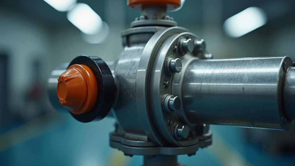
A pneumatic valve actuator converts compressed air into mechanical movement. Rotary actuators are commonly paired with quarter-turn valves such as ball and butterfly valves, while linear actuators can operate valves that require linear stem movement. The actuator, valve and accessories should be selected as one operating package.
This guide covers the information needed for an initial pneumatic actuator selection. Final sizing must use the selected valve manufacturer’s torque or thrust data, the actuator manufacturer’s output data and the actual service conditions.
Double-acting and spring-return operation
Double-acting actuators
Air pressure is used to move the actuator in both directions. The system therefore needs a controlled air supply for opening and closing. The required response following loss of air or electrical control should be considered at system level.
Spring-return actuators
Air pressure drives the actuator in one direction and stored spring force returns it when the air is removed. Depending on the assembly, this may provide fail-closed or fail-open movement. The required fail position is an application decision and must be stated before sizing.
Why valve torque matters
Actuator selection is not based on valve size alone. Valve breakaway, running and seating torque can vary with differential pressure, seat design, temperature, medium, operating history and frequency of operation. The available actuator output also changes with air supply pressure and, for spring-return units, through the stroke.
The sizing calculation should use the minimum dependable air pressure at the actuator, not only the compressor’s nominal setting. Any sizing margin should follow the valve and actuator manufacturers’ recommendations and the project’s operating philosophy. Excessive actuator output can also damage valve components, so simply choosing the largest unit is not a sound approach.
Controls and accessories
- Solenoid valve: switches the air supply in response to the selected electrical control signal.
- Limit switch box or position feedback: reports open, closed or intermediate position as required.
- Positioner: modulates actuator position from a control signal where the valve and process are suitable for control duty.
- Air preparation: filtration, regulation and other treatment should follow the actuator and accessory requirements.
- Speed controls: may be used where opening or closing time needs adjustment, subject to the system design.
Electrical accessories used in hazardous areas require the correct product-specific protection concept, certification and installation. A pneumatic actuator should not be described as making the complete assembly intrinsically safe.
Installation environment and mounting
Confirm ambient temperature, indoor or outdoor location, washdown, dust, corrosion, vibration and any hazardous-area classification. The actuator housing, coatings, fasteners, seals and accessories should be checked for that environment.
The mounting kit and drive adaptor must suit the valve shaft and actuator interface, maintain alignment and transmit the required torque. The valve’s open and closed positions should be verified after assembly, and installation and maintenance should follow the relevant manufacturer instructions.
Pneumatic actuator enquiry checklist
- Valve manufacturer, model, size and current torque data.
- Process medium, differential pressure and temperature range.
- Minimum and maximum available air pressure.
- Double-acting or spring-return operation and required fail position.
- Operating frequency and required opening or closing time.
- Control voltage or signal, indication and positioner requirements.
- Ambient conditions, hazardous-area classification and required documentation.
Find valve actuators and application support
Browse electric and pneumatic valve actuators or send your valve and operating requirements. Valves4You Ltd can help identify a candidate actuator package once the valve data and service conditions are available.